
Transconductance Introduction
Transconductance (gm) measures a JFET's amplification level, correlating drain current (Id) changes to gate-source voltage (Vgs) variations. It's crucial for designing amplifiers with JFETs.
Understanding JFET Operation
A JFET's current conduction between drain and source relies on Vgs. A negative Vgs reduces the current until pinch-off. Transconductance quantifies this control effectiveness.
Calculating Transconductance
Transconductance is calculated using the derivative of Id with respect to Vgs (∂Id/∂Vgs). It's usually given in Siemens (S) and varies along the JFET's characteristic curves.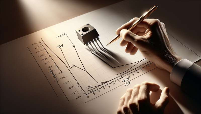
Vgs Impact on gm
At Vgs = -1V and -3V, gm will differ. Typically, gm decreases as Vgs becomes more negative, since less drain current (Id) flows through the JFET.
gm at Quadratic Points
In the quadratic region, the JFET operates with a squared relation of Id to Vgs. Calculating gm requires understanding this non-linear relationship and its effect on amplifier bias.
Biasing With Vgs Variations
Biasing JFETs at different Vgs points affects transconductance and amplifier linearity. A carefully chosen Vgs ensures optimal gm for the desired amplifier performance.
Real-World gm Considerations
In practice, gm varies with temperature and individual JFET characteristics. Precision in biasing and temperature compensation can maintain stable amplifier performance.
What does transconductance measure in JFETs?
Voltage change effect on current
Current change effect on voltage
Amplifier output power levels
Company